Thursday, June 15, 2017

Final Project Blog


FM Transmitter


For our final project, we decided to create a FM transmitter with a microphone input, which would allow us to create a pirate radio station.

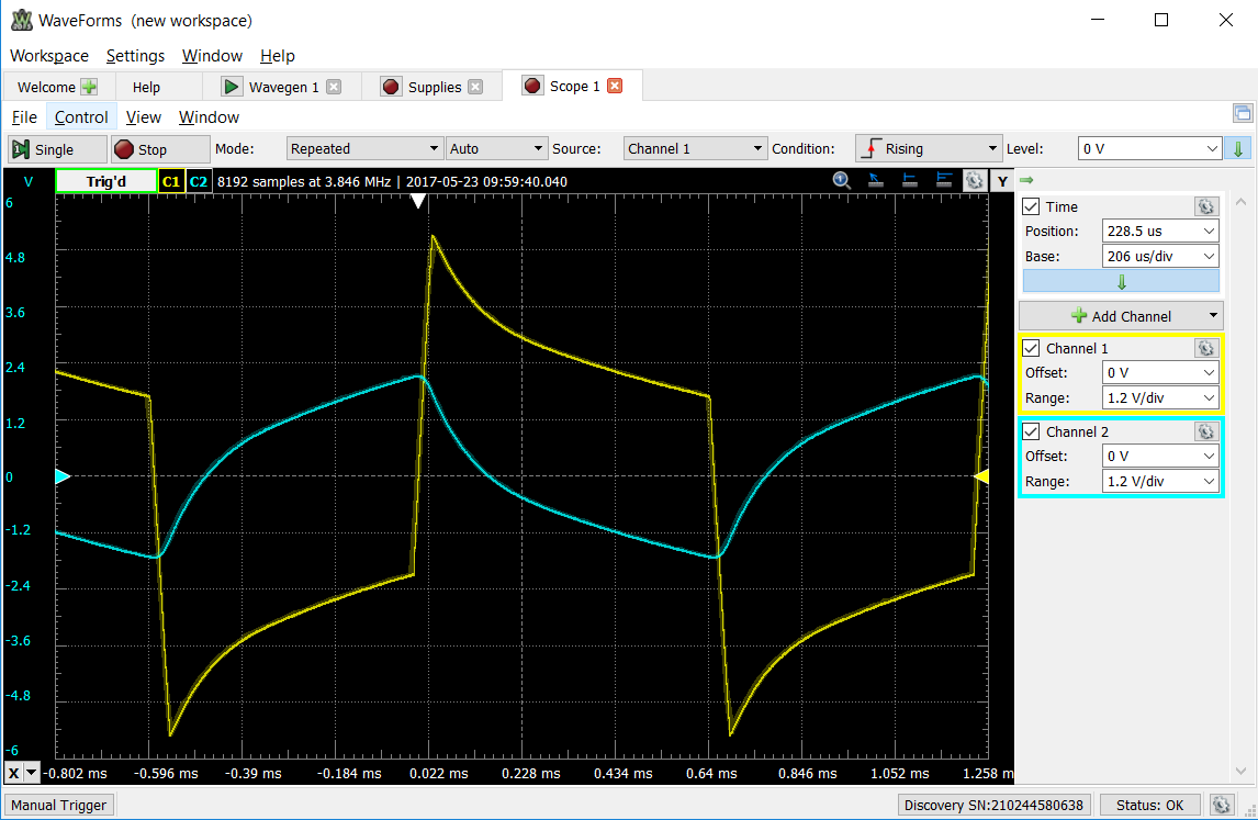
Our initial design was to make it compact enough to fit into altoid box.
Initial sketch:
20170613_061633.jpg

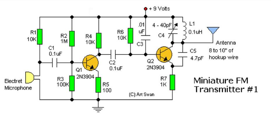
Our schematics for the circuit:


Our first prototype in the breadboard:

20170603_150834.jpg

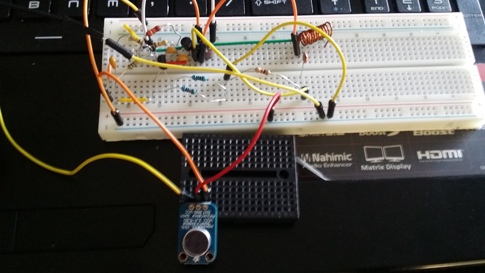
our prototype has the microphone with amplifier as opposed to a regular electret microphone input that we used as our final design. Although this microphone allows us to get voice from longer distance from the mic compared to the regular electret microphone, the component itself is about 3 times the price of our circuit itself, which will increase our production cost by 400% while only increasing the range by only a little bit. We decided that the cost outweigh the benefit, and decided to use a regular electret microphone instet.

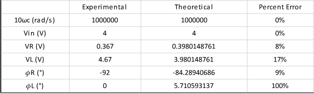
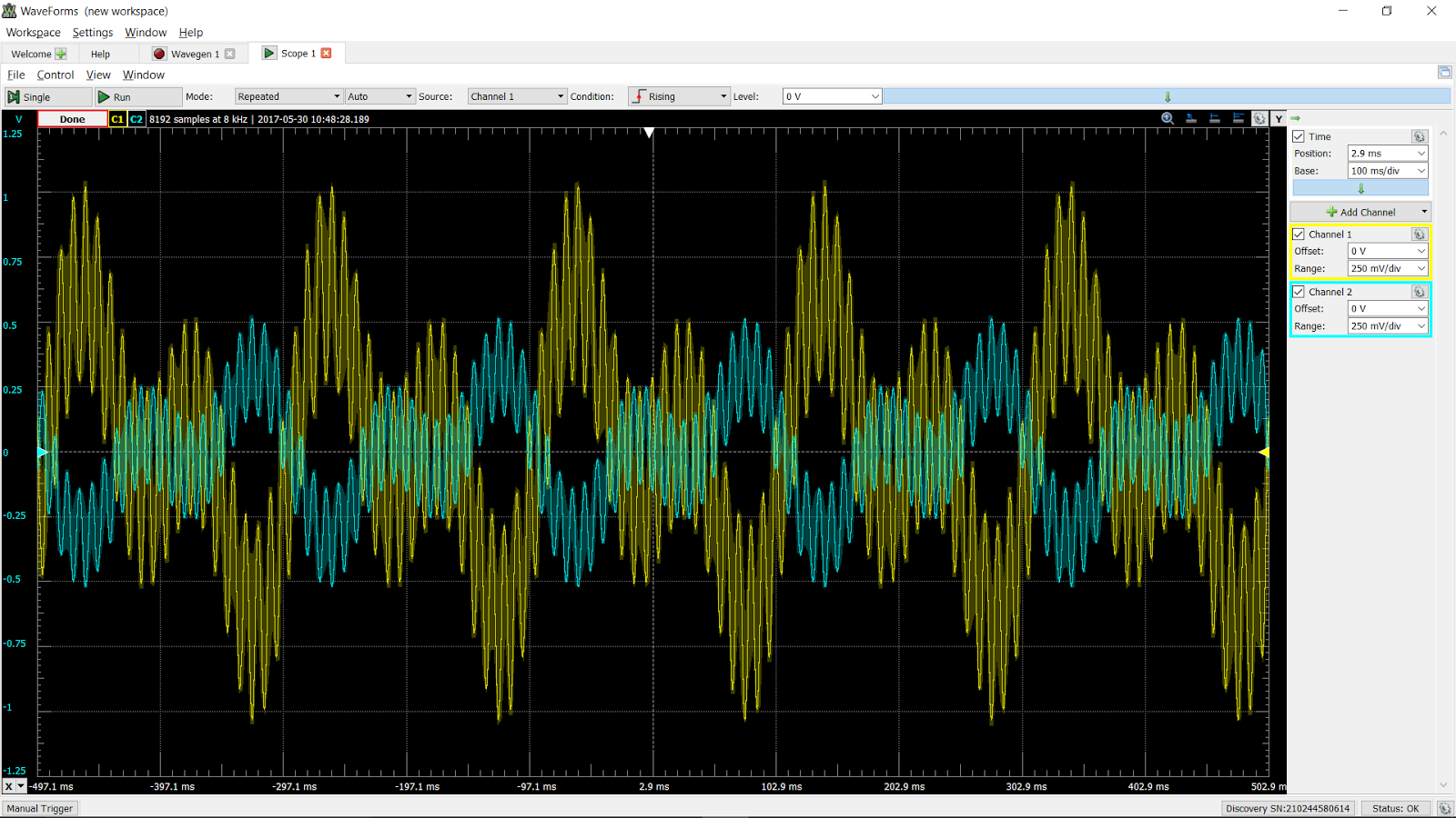
At the testing stage, we met with a couple difficulty, such as:
- trying to debug why our circuit did not work, when it was actually working but our radio was just not good enough to recieve signal (we initially used fm radio app that comes with our phone, and it will lose the signal just by orienting it differently).

-  when we used waveform to test the circuit, there were 2 frequencies where the signal could be heard. One is at the 90MHz range, which comes from the analog discovery box, and another is at the 80-90MHz range, which comes from the circuit. We spent a lot of time trying to figure out why our trimmer capacitor did not change the frequency, but it turns out it was because we were tuning to the analog discovery signal.

- We did not have a nonconductive screwdriver, which make our circuit to change frequency just as we take off our screwdriver off the trimmer capacitor, which was not great. We later tried to resolve it by plasti-dipping our screwdriver, which helps the tuning process easier because it is nonconductive(ish).


- noises in our broadcast. This happened when we used too much gain in the microphone or when our media player is at a high volume (when using a 3.5 mm audio jack input). 

We also created a prototype with a 3.5 mm audio jack input as aforementioned:

20170613_060550.jpg

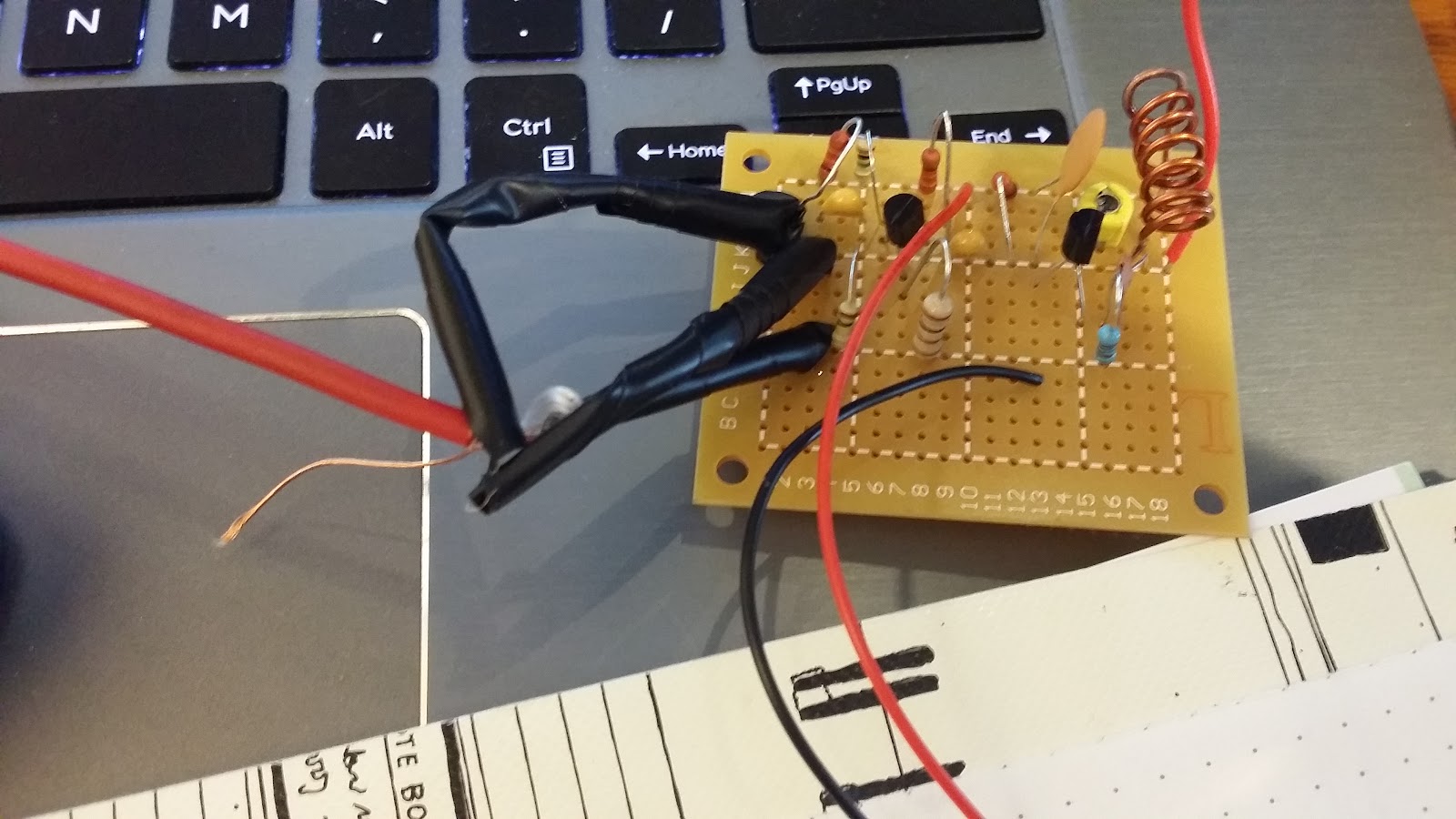
Also, using Perfboard as opposed to the breadboard make our broadcast to be clearer by quite a bit.

Our final design:

 20170613_065118.jpg

Our microphone input:

20170613_065059.jpg


We added a solid wire as a structural support to our antenna because we found that by twisting the antenna differently, we will change the frequency of our broadcast, which we found to be non-ideal.

If we were to have more time, we would switcch our input to two jumper wires instead, so that we could hook it up to a mini breadboard that has different inputs ( mic or audio jack), which would allow for easily swappable input, which will make our design more versatile.


6/8/2017 Classroom Activities + "Passive RL Circuit Response" lab

6/8/2017

Today we first learn about how to calculate the omega_0 and the cutoff omegas of a parallel RLC circuit. At the cutoff omegas, the power is half the max power which occurs at omega_0.


We then were assigned to find the voltage gain of a circuit


We also learn how to calculate cutoff frequency of a circuit


"Passive RL Circuit Response" lab:


for the prelab, we were told to find the cutoff frequency of the RL circuit, which we found to be at 10^5/2pi

For RL circuits, the high pass filter occurs when we take the output of the inductor, and low pass occur when we take the output of the resistor.

Our obtained graph when it is low frequency (at omega=omega_c/10)


Graph when it is high frequency (at omega = 8* omega_c)


Note that the red(math channel) is for the input voltage, yellow is the output voltage of the resistor, and the blue is the voltage of the capacitor.

Comparing the experimental and theoretical values:


Conclusion:

From this experiment, we could see that the phase shift between the input voltage and the resistor voltage is close to 0 at low frequency, and the phase shift between input voltage and the inductor voltage is close to 0 at high frequency. There is a 90 degree shift between input voltage and resistor voltage at high frequency (resistor voltage is leading by 90), and 90 degree shift between input voltage and inductor at low frequency( inductor voltage is lagging by 90)


6/6/2017 Classroom Activities

6/6/2017

Today we learned how to construct bode plots, which consists of gain(dB) vs frequency, and phase shift vs frequency. Both of the graphs are approximation of how the graph will look like, using a semilogx graph.


We also learn a little about filter, and finding the peak frequency (omega_0) and the cutoff frequencies at which point the voltage is 1/sqrt(2) times the maximum voltage.


5/30/2017 + "Signals with Multiple Frequency Components" Lab

5/30/2017

Lecture:

Today we learned about constructing the transfer function <H(omega)>. Transfer function could be one of the 4 things: Voltage gain, current gain, impedance, and admittance. We could let omega*j to be s, which would simplify the ratio more, and finds the zeros and poles of the function. Zeros is when numerator is zero, poles is when denominator is equal to zero.


"Signals with Multiple Frequency Components" Lab

Prelab: 

We were assigned to calculate the gain as omega approaches zero and as omega approaches infinity


Our circuit:


In this lab we learned how to create a custom voltage input in waveform. 

The graph obtained from the custom input voltage vs the output voltage(green input, blue output):


We then did a frequency sweep:


Conclusion: 

From this experiment, we see that as omega approaches 0, the voltage gain of the circuit is 1/2, and as it approaches infinity, the voltage gain is 0. We could see from the graph that when it first started, the Vout (blue) is close to half the value of the Vin(green), and as omega goes higher, the ratio of Vout/Vin gets smaller and smaller.


Monday, May 29, 2017

5/25/2017 Classroom Activities+ "Apparent Power and Power Factor " Lab

5/25/2017

We derived how to find effective current, which at the end is equal to rms current, and finding amplitude of voltage given the value of Vrms


Practice on parametrizing a curve:


Finding Irms, apparent power, and power factor of a circuit


Finding complex power:


"Apparent Power and Power Factor " Lab

Prelab:

Waveform on the circuit with the second resistor having the value of 10 ohm


Waveform on the circuit with the second resistor having the value of 47 ohm


Waveform on the circuit with the second resistor having the value of 10 ohm

 Comparing the theoretical and experimental values

On the circuit with the second resistor having the value of 10 ohm


On the circuit with the second resistor having the value of 47 ohm


On the circuit with the second resistor having the value of 100 ohm


Summary:

We could calculate I rms and V rms by divinding I and V with square root of 2 respectively. We could calculate the average power by multiplying Irms and Vrms. We could also calculate the power factor by calculating the ratio of the real part of the power to the magnitude of the complex power., and taking the arc cosine of the angle. Also, there is a "measure" option in waveform that calculates the rms value while collecting data.


5/23/2017 + "Op-Amp relaxation Oscillator" Lab

5/23/2017

Problem involving op amp and using nodal analysis to solve it


We were then assigned to find the output voltage of an op-amp with no open loop gain


Finding instaneous power


Finding current and the equivalent impedance of a circuit


"Op-Amp relaxation Oscillator" Lab

Prelab(finding a combination of resistor and capacitorthat would output a frequency of one's last 3 digit on student id):

Everycircuit on the proposed resistor and capacitor combo:


The circuit:


The components:


Waveform of the voltage across the 7.3k resistor


Waveform of the voltage across the 7.3k resistor(yellow) and the capacitor(blue)


Waveform of the voltage across the two 1k resistor(yellow) and the capacitor(blue)


Values comparing the theoretical and experimental frequency


Summary:

Everycircuit has the "inject noise" option, where by dragging and shaking the circuit, it allows us to make a circuit without a power supply and still read its values (circuits with capacitors and op amp inside). From the experiment, we could see that the theoretical and measured frequency across the 7.3k resistor(the one we fiddled with) are pretty close to each other. It shows that we could create a circuit with a desired frequency by changing the combination of the capacitor and the feedback resistor. Also, by leaving the two resistance near the ground to be equal to each other, we make the calculation for the desired frequency much easier for ourselves.