Wednesday, March 29, 2017

3/28 Class Notes + "Thevenin's Theorem" Lab


3/28/2017

Today we were taught of Thevenin's way of finding Thevenin's voltage and Thevin's resistance, which could be used to find max power.
Here is an example of finding Thevenin's voltage and resistance:


 After using derivation, we could find the equation, where

max power = (Vth)^2 / (4*Rth) 

Here is an  example of solving for Max power:


Also, note that sometimes Rth could be negative, it just means that the circuit is supplying power.

Right at the end of class, we learn of Norton's current, which is the equivalence of Thevenin's Voltage and Thevenin's Resistance transformed using the source transformation method.
Here is an example we did on Norton's current:


"Thevenin's Theorem" Lab

Prelab:

Finding Vth theoretical:


Finding Rth theoretical:


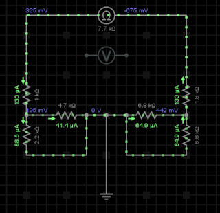
Both of the values also checks out when we tried to plug in using everycircuit:


Here are the values of the resistors that we uses:

First 6.8k ohm resistor


Sccond 6.8k ohm resistor


4.7 k ohm resistor


2.2k ohm resistor


1.8k ohm resistor


1k ohm resistor


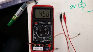
Thevenin voltage experimental:


Thevenin Resistance experimental:


                                                                                                                                                                    We then connected a potentiometer, adjusting its resistance, and tested for the voltage difference, collecting voltage data at different resistances:
                                            

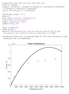
Using the trendline from excel, we make a mathematical model in matlab, which tells us that the maximum voltage should occur when R= 7.5k ohms, which is 2.667% different than the theoretical that should make the R=7.7k ohms. 


Summary:
Thevenin is a genius that enables us to find maximum power using less time. Maximum power is obtained when we set R to be equal to R thevenin, which will gives us a power of 
max power = (Vth)^2 / (4*Rth) 
Also, potentiometer is pretty neat because it allows us to adjust resistance on the go.


Sunday, March 26, 2017

3/23/2017 Class Notes + "Superposition" Lab


3/23/2017

Class Notes:

To start the day, Professor Mason talk about linearity, and how linearity plays a role in circuit. ENGR 44 focuses on linear circuits, where the input is equal to the output. First we did a sample question linearity.

Then we talked about how using linearity we could easily solve for current and voltage by "guessing" the initial voltage drop of a resistor as 1V. After guessing the inital voltage drop as 1, then we find the current if voltage drop were to be 1. After that we find by what factor is the voltage off by. We then multiply the factor to our initial guess of 1, which will give the actual voltage drop over that resistor.

Professor Mason then taught us the art of superposition, which is the fancy term for addition.
Superposition in a linear circuit works wonders! For example if there are 2 voltage sources in the circuit, superposition allows us to calculate by adding the voltages in the 2 circuits which only has 1 voltage source each. It also works on current sources too.
In the case that there is a voltage source and a current source in the circuit,
when we solve for the voltage from the voltage source, we treat the current source as if it is an open circuit.
On the other hand, when we want to solve for the voltage from the current source, we short the circuit, treating the voltage source just as a regular line/connection.

Professor Mason also taught us the art of transforming a voltage source into a current source, and vice versa. The transformation from a voltage source to a current source requires that there is a resistor connected into the voltage source in series, which will then be transformed into a current source that is connected into the resistor with the same resistance in parallel. The current source would have the value of the voltage of the voltage source divided by the resistor.
The other process would be the exact opposite. It requires a current source that is connected to the circuit in parallel, which would then be converted to a current source connected to a resistor with the same resistance in series. The voltage source have the value of the current from the current source multiplied by the resistance of the resistor.
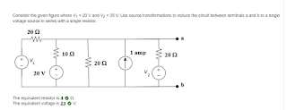
Why is this technique important, one might ask? Well, it could replace a complicated looking part of circuit to a much simpler, like this homework problem

Pretty neat!

Professor Mason also taught us the magic of "everycircuit", which is an awesome tool to check our work with.


"Superposition II " lab

Prelab:

As usual, we change the 20k to a 22k resistor because we don't have a 20k resistor :(

Resistor values:
the "10k":

the "4.7k":

the "6.8k":

the "1k":

the"22k" (a.k.a the poor man's 20k):


Setup:


We first turn on both power supply and measure the voltage drop across the 6.8k ohm resistor,
and we manage to get a 2.70 V drop over it:


We then turn off the  3V voltage source, leaving the 5V voltage source as the only voltage source, which gives us a voltage drop of 1.99V across the 6.8k ohm resistor, giving us a % error of 0.15%.


Something weird happen when we leave the 3V voltage source as the only voltage source, because it gives us a voltage drop of 1.03 V across the 6.8k ohm resistor, which is about 45% error compared to the .708 V theoretical voltage drop that we calculated in the prelab.


The "fix" happens when Jeremy shorted the 5V completely, giving us a reading of .70V, which is only 1.13% error compared to the theoretical voltage drop.


The weird thing is when whether we shorted the 3V or not, we ended up with the same value of  1.99V.
The total voltage drop across the 6.8k ohm resistor when we used superposition without shorting the circuit would be 3.02V, which is about 12.1% error compared to the 2.695 as calculated in the prelab, while if properly shorted the superposition would give a total voltage drop across the 6.8k ohm resistor of 2.70, giving a % error of a tiny amount of 0.19%.

Summary:
When doing superposition in a breadboard circuit using analog discovery box as a power supply, make sure to properly short the unused power supply, in case that it gives a weird value like the 5V power supply. According to Professor Mason, this might be caused by the internal resistance that the box might have. In any case, better safe than sorry.
Also , using superposition and transformation could save so much time in calculating the circuit.
Last but not least, everycircuit is a new tool in our toolbox to check our answer in case we ran out of "check my work" tries in connect homework.

Tuesday, March 21, 2017

3/21/2017 Classwork + "Mesh Analysis 2" Lab + "Time Varying Signals" Lab

3/21/2017

Class notes:
Today we finished up on Mesh analysis.  We were taught an easier way to reduce the amount of algebra in doing mesh analysis.
instead of doing

we could instead count separate them by each current. I.e. for counting i1 we could just do
12i1-6-2i2=0; which reduces the algebra by one line.
We learned about transistors, diodes, and doping.
Firstly we were taught on diode, where the arrow on the diagram shows the direction of the current.
Professor Mason then talked about doping, the process where a more electronegative/electropositive element is introduced to semiconductors like Silicon and germanium . If the process of doping uses a more electronegative element, then it will create an N type (negatively doped) semiconductor.
In order to create a diode, a p type and an n type is placed next to each other, which in turn create a "depletion zone" in the middle of the two. This zone has a balanced charge, which makes it hard for current to go through.
We also were taught on transistor (namely the BJT type), and were given some problem to solve regarding power, voltage, and current of a circuit with a BJT.


Lab:

- "Mesh Analysis 2" Lab

Setup:

Hand calculation on the theoretical value of the circuit


Different Values of the resistors:


Experimental value of the voltage drop in the 6.8k ohm resistor:


Experimental current going through the 10k ohm resistor


The voltage across the 10k ohm resistor


Setup of the breadboard :


*Note: We used 22k ohms resistor instead of the 20k resistor because there isn't any in the lab.

Theoretical value:
Based on the value that were printed out on the transistors, we got
I1= -.322 mA, and V1=5 V.

Experimental value:
We found that V1= 4.99V, and I1=.362 mA.

Comparing the theoretical and experimental value, we found that there is a .20% difference regarding V1, while I1 has 11.80% difference.

- "Time Varying Signals" Lab


Ramp up function in the wavegen

Ramp up function in the scope


Sin function in Wavegen


Sin function in scope


Summary:
- It is important to practice setting up the scope window to produce graph that is needed for the experiment result.
- Solving transistor by changing it to a current source and a voltage and a voltage source enables us to solve for a circuit using the things we have learned


Monday, March 20, 2017

3/16/2017 Mesh Analysis+ "NODAL ANALYSIS LAB"

3/16/2017

We started the class by doing "Nodal Analysis Lab"

Setup:

Measuring the resistance of the resistors


Making sure the power supply is 3V


Voltage across each resistors:


The rather messy one ( the setup that is used for regular ungrounded 3v power supply)


We change it around after knowing the black box is grounded;


Final setup (SO MUCH CLEANER THAN BEFORE!)


****Note****
-Turns out in the analog discovery box, it is internally grounded. This makes it unnecessary to put more grounding cable as if we would if we use regular power supply.
- Red cable is always +5V , while  white cable is always -5 V. Yellow cable is adjustable through the wavegen tab.


Class notes:


Mesh analysis

Mesh analysis differs from nodal analysis in that one analyzes voltage, whereas the other one analyzes current.

Mesh is a loop that doesn't have any other loops within it.

When there is a current source that is in the middle of two meshes, we could combine them into a SUPERMESH!

Mesh analysis is only usable in planar circuit.


Summary:
- Analog discovery box enable us to reduce the number of cable needed vs. when we uses conventional power supply.
- I learn that we could have more than just 2 power supply out of the analog discovery box (3 that we uses today).
Mesh analysis is useful, but not usable in anything other than planar circuit.