We derived how to find effective current, which at the end is equal to rms current, and finding amplitude of voltage given the value of Vrms

Practice on parametrizing a curve:

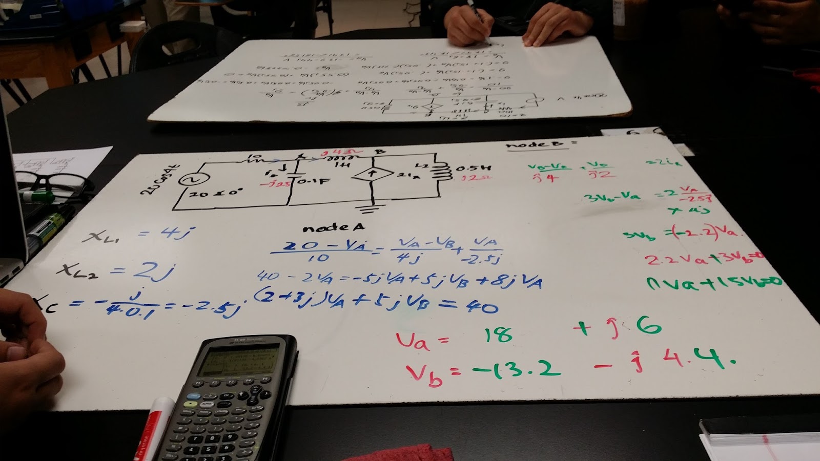
Finding Irms, apparent power, and power factor of a circuit

Finding complex power:

"Apparent Power and Power Factor " Lab
Prelab:

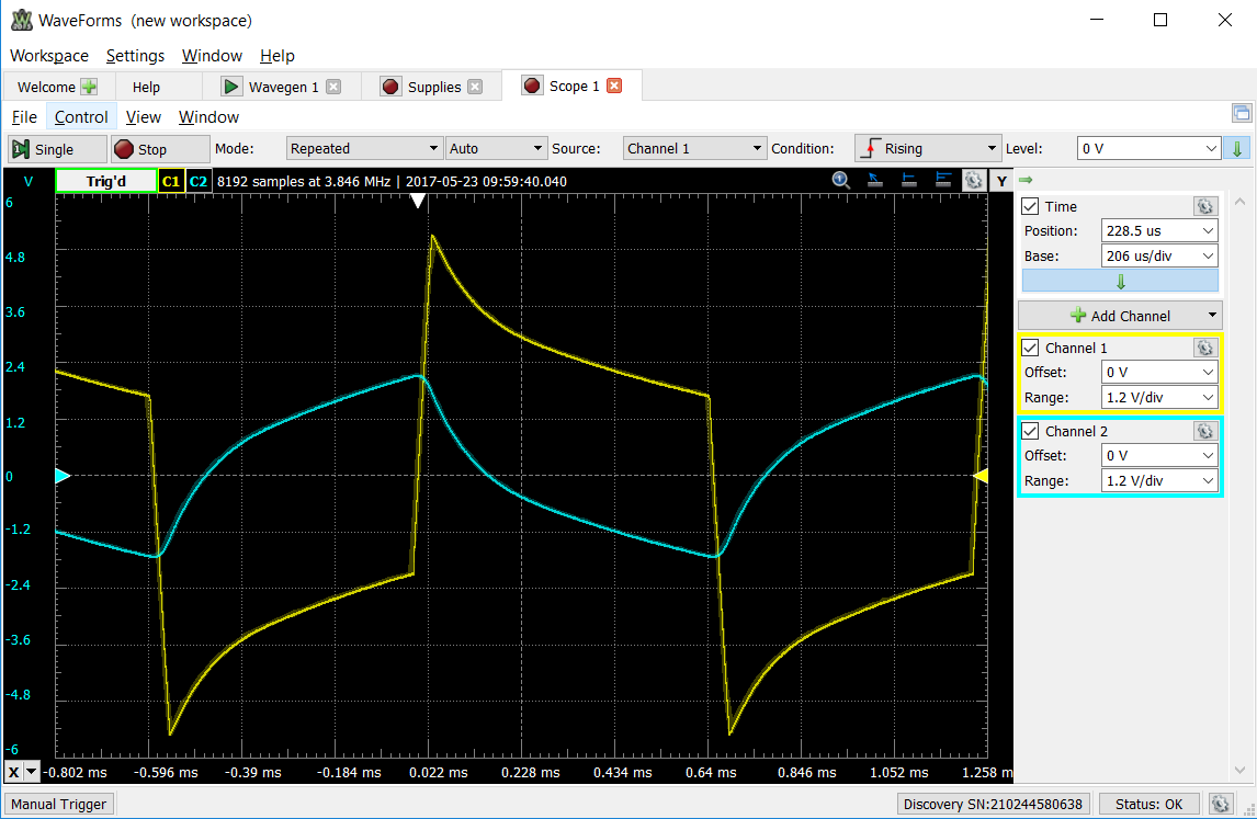
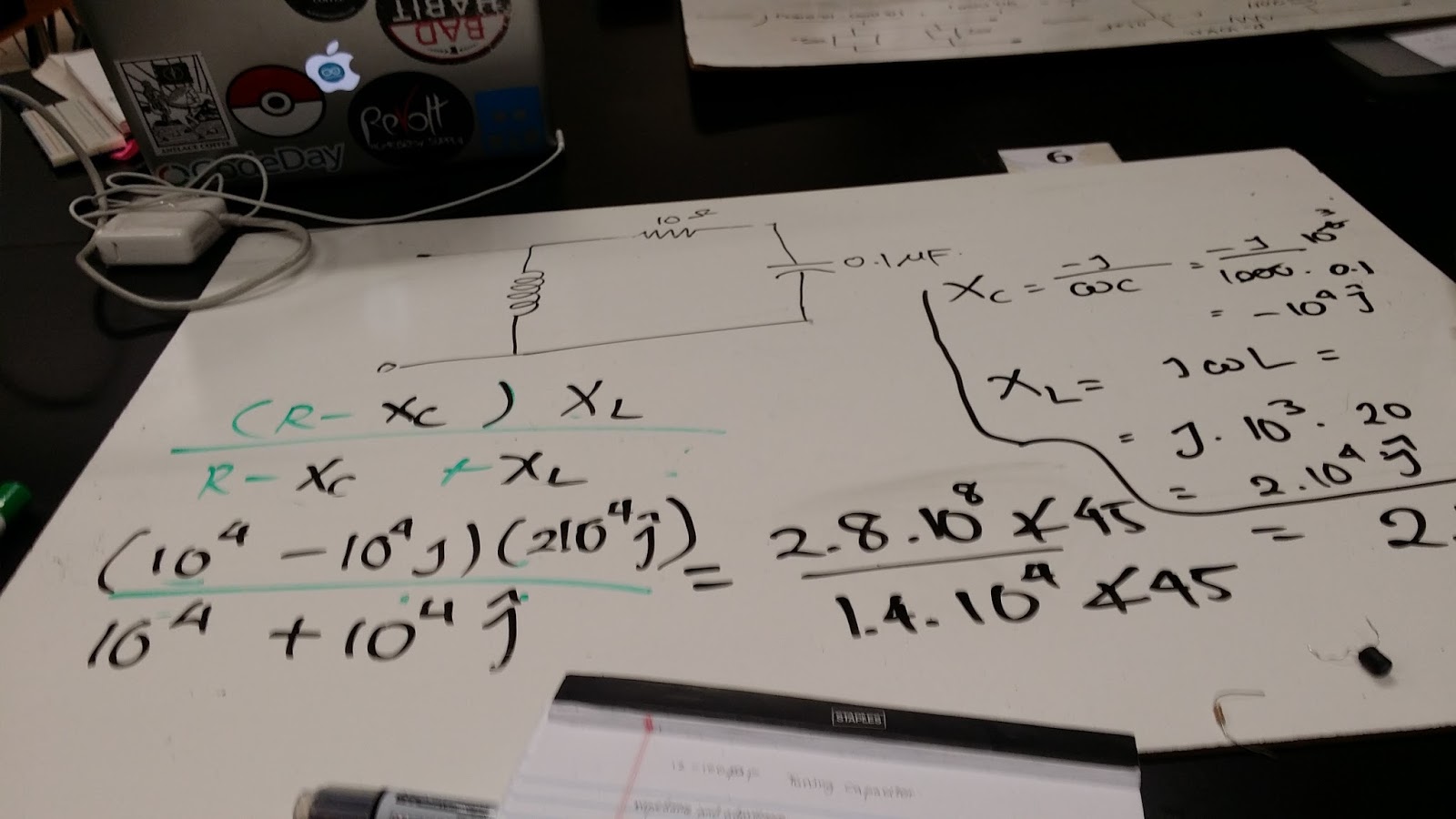
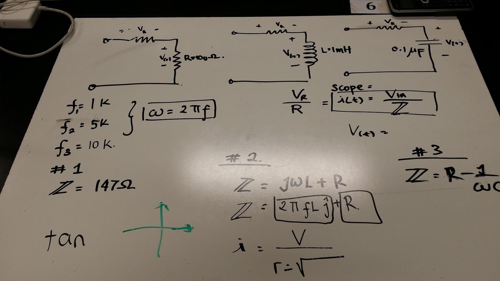
Waveform on the circuit with the second resistor having the value of 10 ohm

Waveform on the circuit with the second resistor having the value of 47 ohm

Waveform on the circuit with the second resistor having the value of 10 ohm

Comparing the theoretical and experimental values
On the circuit with the second resistor having the value of 10 ohm

On the circuit with the second resistor having the value of 47 ohm

On the circuit with the second resistor having the value of 100 ohm

Summary:
We could calculate I rms and V rms by divinding I and V with square root of 2 respectively. We could calculate the average power by multiplying Irms and Vrms. We could also calculate the power factor by calculating the ratio of the real part of the power to the magnitude of the complex power., and taking the arc cosine of the angle. Also, there is a "measure" option in waveform that calculates the rms value while collecting data.