We started the class today by Professor Mason demonstrating the suicidal sausage experiment. We were told to discuss with our group whether the sausage will be 1)slowly cooked, 2) not cooked, or 3) explode. We were also asked how the current vs time graph will look like on this sausage.
The current should be decreasing overtime as sausage loses moisture from being slowly cooked.
Then the professor went and put some LEDs on the sausage, some in series and some in parallel. We were asked how the LEDs will behave. It turns out that the LEDs perpendicular to the sausage would not light up, while the parallel ones light up, at least until the current approaches 0 as the sausage gets higher resistance from being cooked, which would make the LEDs to not light up.
We were then asked to predict the value of a current and voltage of a CCCS circuit, like one pictured above.
In the picture above, we were asked to find the value of V_out, which could be found from reducing the voltage from the power supply with the voltage of the first resistor, which we could find after we calculate for the current.
The professor points out the major difference between a science class and engineering class. Whereas we would be using = sign in science class regarding numbers, engineering should use more inequality signs because custom manufacturing would be more costly compared to getting one that are mass produced.
In the picture above, we were told to find the upper/lower bound of R2 which would work well with our diode, and find the resistor that is ideal for this circuit. Since we found the bound to be within 3.33 and 10, the best resistor that we can find and use in this class would be the 7.5 ohm resistor. Also, I learned that we treat diode as a voltage sink and not a resistor when we calculate the circuit.
We then went over calculating total resistance of circuit (stuff that we cover from physics class), pictured above.
The picture above is the solutions that we come up when photocell acts as a 5k ohm resistor and a 20k ohm resistor.
We measured the resistor in the circuit to be 9.84 k ohms.
The photocell turns to be showing a value of about .6 to .7 kilo ohms when exposed to bright light from cellphone flashlight.
In darkness, it goes significantly to 15 kilo ohms when lightly covered, and infinity resistance when covered.
The pictures below were the setup that we used first, which is wrong. This setup was wrong because we switched the diode (long-short one), and using a negative voltage to power it up. Turns out the photocell still works, but not as significant as the one that were supposed to be. It kinds of dim and brightens up, when photocell is being played with (with V around 2.55 to 3.88), but not really to the point where the light is completely off.
We then switched the sides of the diode, fixed our voltage issues, and run it using positive voltage. The end result is the light completely off when photocell is not covered, and goes bright when it is properly covered, refer to pictures below.
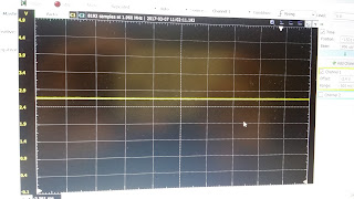
Here are some of the pictures of the voltage of the photocell (above: when photocell is not covered, below is when it is completely covered)
Here are some gifs on the right setup that we did:
Summary:
Voltage goes up as the photocell is open, and goes down when photocell is covered. When the photocell is covered, it increases its resistance, which in turn reduces the current, making the current to go through the diode. The diode then becomes brighter as a result, which is in accordance to the result observed.


No comments:
Post a Comment