The class begins with Professor Mason asking us our prediction of inductor and capacitor in a DC circuit, and also why ragebridge makes spark when it first turn on.
We then were told to derive the unit of permittivity:
After that we derive how capacitor would behave in a dc circuit after it is charged, where it would act as open circuit.
We then practice on getting equivalence capacitance in a circuit , where parallel would add up their capacitance, while series would add the inverses of the capacitance(the calculation of capacitance equivalence in series is like resistor in parallel, and vice versa).
After that we derive the relation between current and voltage in capacitor:
We also derive the relation between current and voltage in inductors:
Professor Mason finally showed us something cool, where he blew up an electrolytic capacitor:
well the fried sausage demo was pretty good, but nowhere close to this demo (more explosion demo please!).
This explosion happen when the capacitor is fed electricity from its negative side and not its opposite side. This is the negative side of a capacitor( it has - sign posted there):
"Capacitor Voltage-current Relations" Lab:
Prelab:
Circuit design for the experiment, and the prediction of the current vs voltage graph in the cases of cos function and a triangle function:
This lab's circuit is pretty simple in design, but I learn that we actually has 2 scopes in the analog discovery, where it is the previously known orange-orange white as the first scope and blue-blue white cable as the second scope.
Closeup of the circuit:
Datas obtained:
- Using sin function in the wavegen with a frequency of 1kHz:
The cosine wavegen aka the sin wave offset by 90 degrees
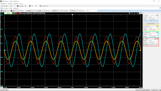
The scope, where the blue one is the voltage measuring the capacitor voltage, yellow is the one measuring the voltage difference across the resistor, and red(orange?) is the current going through the resistor, which is obtained using the math function by dividing the voltage across the resistor by 100 (the resistance of the resistor).
a not so exciting gif ( it stayed in place ;( )
- Using the sin function in the wavegen at 2kHz frequency:
'cosine' wavegen at f=2kHz
The scope, similar to the previous one, where the blue one is the voltage measuring the capacitor voltage, yellow is the one measuring the voltage difference across the resistor, and red(orange?) is the current going through the resistor, which is obtained using the math function by dividing the voltage across the resistor by 100 (the resistance of the resistor).
Another not so obvious gif attempt that looks like a still picture :(
- Using the triangle function with f=100 Hz:
Triangle on the wavegen, phaseshifted by 90 degree
Triangle function, where blue = voltage across the capacitor, yellow is the voltage across the resistor, and red(orange?) is the current across the resistor obtained from the custom math function by dividing the voltage across the resistor by 100.
We noticed that the current graph is not as square as we had expected, which Professor Mason said that it was due to the acceleration also having derivatives like snap, crackle, and pop, which makes it highly impossible to be dropping in a square manner, and instead work in a continuous manner, making that graph.
here is the gif of the triangle function . Notice that they are always 90 degree out of phase.
"Inductor Voltage-current Relations" Lab
Well the prelab for this lab is exactly like the one in the "Capacitor Voltage- current Relations" lab, with the difference being we are using an inductor in the place of the capacitor. We redid the sketch of the current for the inductor, whereas instead of taking the derivative of the voltage, we integrate the voltage, where we end up with a positive sin function rather than a negative sin function
Picture of the circuit:
That inductor is larger by quite a bit compared to the capacitor used from the previous activity.
Here is the graphs obtained:
- sin function with f=1kHz:
Instead of the - sin current like the one from the capacitor, we get a + sin current when paired up with a cos voltage. There is a slight phase shift between the two compared to the one in the capacitor, which Professor Mason said to have something to do with the coil within the inductors.
- Sin function with f=2kHz:
This one has slightly closer to 90 degree phase shift between the two as opposed to the first one.
Summary:
Capacitor's relation between voltage and current is that the current is the derivative of the voltage(the slope of the voltage graph). The Inductor's relation between voltage and current is that the current is the integral of the voltage(the area of the voltage graph).


No comments:
Post a Comment