Class notes:
First problem we get to predict Vout when Vin is a time varying signal; with an op amp having +9 as the positive rail and 0 as the opposite rail, and time varying signal between -.1 V to +.1V:
Second problem we change the signal to the range from 0 to 200 mV. This theoretically should give a negative Vout; however, since the negative rail of the Vout is at 0, it will just output 0.
Third in class problem we get to solve for the Vout in another inverting op amp circuit.
We were then given the task to derive a difference op amp from the problem in the projector;
here is our derivation:
We then were told to analyze a circuit:
Our calculation:
which also matches with the answer we got from everycircuit:
LAB:
"Summer Amplifier":
Prelab:
Here we are designing a summer op amp, in which Vout=V1+V2
Here is our first 10k resistor:
Here is our second 10k resistor:
Here is our third 10k resistor:
No, it was not a picture of a single resistor taken 3 times; we actually take some time to find the 3 resistors that are closest to each other to get the best result for our experiment.
Here is our beautiful circuit:
Here is our experiment where we put 0.5V to both V inputs:
Here are the results from our "Summing Amplifier" Lab:
"Difference Amplifier" Lab:
Prelab:
Designing a difference op amp circuit with a gain of 2:
We then measured two resistors of 20k values;
Picture of our Difference amplifier circuit:
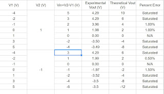
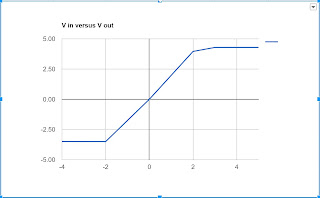
Values and graphs obtained:
graph when v2=1V
graph when v2=-1V
Summary:
When creating a summing amplifier circuit using resistors of the same values for input resistances and rf, we manage to get a v out of -(v1+v2).
When creating a difference amplifier using 4 resistances where 2 of them (the one connected to the input voltages)has the same value, and the other 2 also has same ratio, we could get the gain as the ratio of the two different values of the resistors.
Also, problem about saturation also happens on this lab as observed from the last lab ("Inverting voltage amplifier").


No comments:
Post a Comment