We started the day by drawing a phasor diagram and how we think it would look like for resistor, capacitor, and inductor

We then find the impedance of elements when the angular frequency approaches infinity

We also practiced on finding current of a circuit with a voltage source

After the lab, we went on to find the equivalent impedance of a circuit
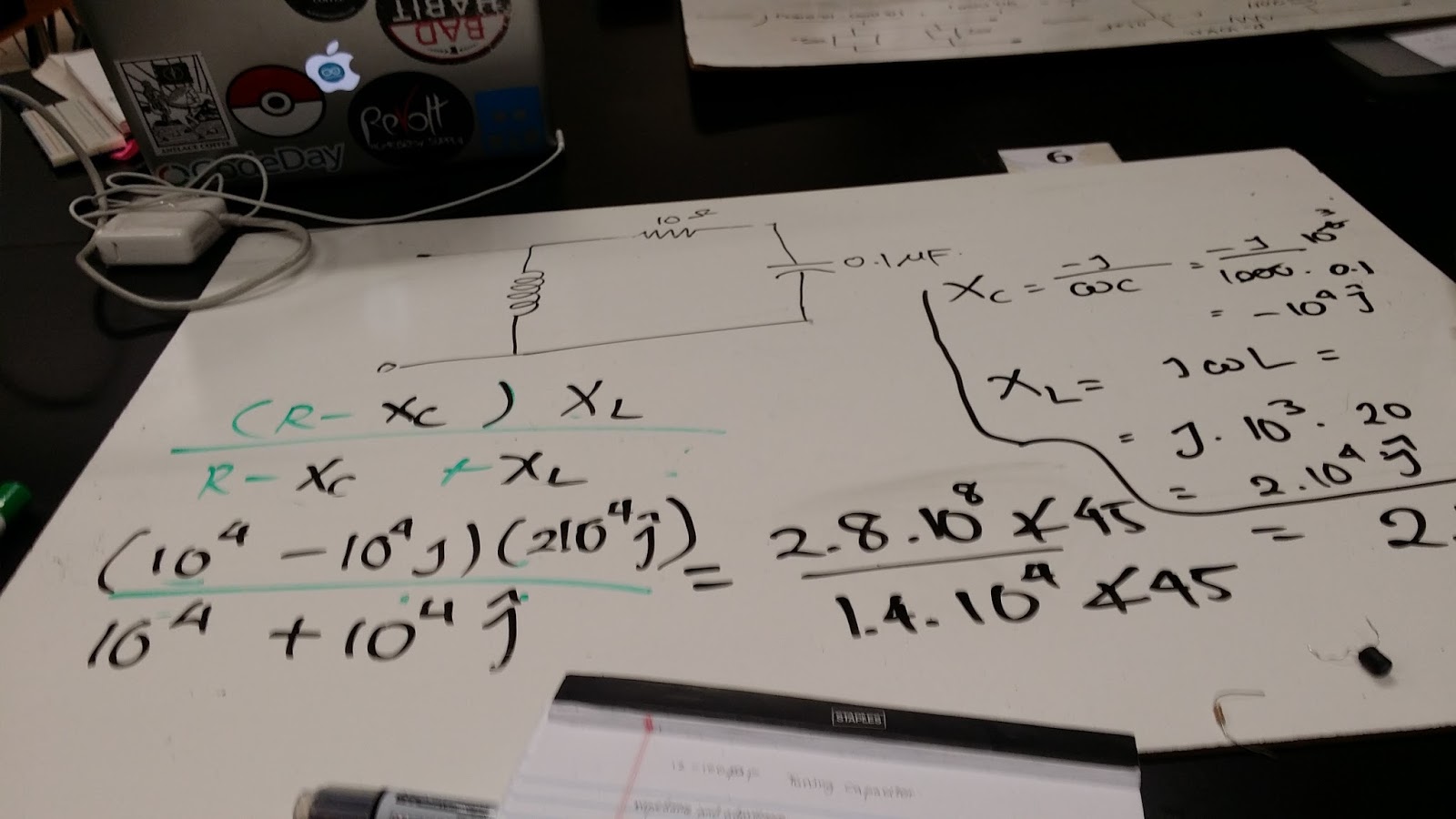
We also did a problem finding an equivalent impedance and also finding the voltage across one of the elements

"Impedance" Lab
Prelab:
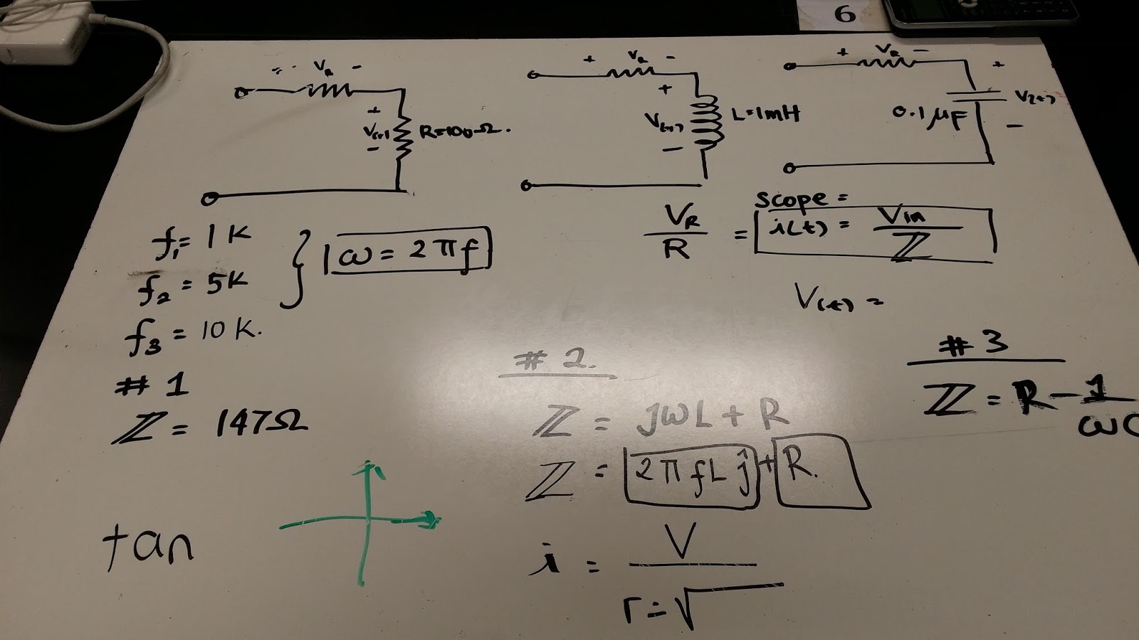
Waveform for the Resistor as the second element:
at f=1kHz

at f=5kHz

at f=10kHz

Waveform for the Capacitor as the second element:
at f=1kHz

at f=5kHz

at f=10kHz

Waveform for the Inductor as the second element:
at f=1kHz

at f=5kHz

at f=10kHz

Values:

Summary:
As predicted, current and voltage are in phase for resistors, current leads voltage for capacitors, and current lags voltage for inductors. For Inductors, the phase difference increases as angular frequency increases, and decreases as angular frequency decreases. It is the opposite for capacitors; phase difference decreases as angular frequency increases, and increases as angular frequency decreases. The theoretical and experimental values are pretty close to each other, which means that the formula used to find impedance of the elements holds true.
No comments:
Post a Comment