5/9/2017
Today we were taught the step response of both series and parallel RLC circuit.
First we were taught the step response of Series RLC circuit. Basically the voltage of the capacitor as a function of time will have 2 parts, the natural response which will die out with time, and a forced response, which is the voltage coming from the voltage source. We did a practice problem regarding step response of series RLC circuit:
We then went over step response of parallel RLC circuit. For parallel RLC circuit, instead of using KVL, we are applying KCL to the system. The equations come out pretty much the same as the series RLC circuit, but instead of relating it to voltage we relate it to the current. Practice problem regarding step response of parallel RLC circuit:
"RLC Circuit Response Lab"
Prelab:
We then went over finding the natural frequencies, neper frequency, resonant frequency, and the damped natural frequency:
Picture of our circuit:
Resistor Value:
Our wavegen graph that we get
Our values:

Summary:
Using the technique learned to solve the step response of parallel RLC circuit, we could calculate the values of current and voltage of the different elements in this circuit, with slightly changing the formula for the voltage due to the extra resistor in the back of the inductor. We see some underdamping case again for this experiment, although it is not so large as the one that we see in the previous experiment. I found it pretty interesting how our Vin is also damped to some degree when it is seen in the oscilloscope.
Monday, May 29, 2017
5/2/2017 Classroom Activities + "Series RLC Circuit Step Response"
5/2/2017
Classroom Activities
Today we started by doing initial value problem:
We did this on our whiteboards, and ended up with
After that we went over the source free series RLC circuit, where we were assigned to find the second order linear equation for a source free RLC circuit;
We then did a practice example of using the formula above to find natural frequencies of a circuit
After lab, we went over the source free parallel RLC circuit. Turns out alpha changes from the R/2L value in the case of source free series RLC circuit to 1/2RC for source free parallel RLC circuit. We also did a practice example of the case involving source free parallel RLC circuit
"Series RLC circuit Step Response" Lab
For prelab, we were assigned to solve the second order differential equation for our circuit. From the values given, our circuit would be highly likely to undergo an underdamped case.
A picture of our circuit:
Value of the resistor; it is around 1 but it shows 3, we suspect it is the internal resistance that might come from the gator clips, since it shows 2 when we just touched the clips together.
Value of the capacitor
Waveform Result:
Still picture when it goes negative overshoot
Still picture when it goes positive overshoot
Summary:
For resistors with small resistances, the value read on the DMM might be affected quite significantly due to the internal resistance of the DMM itself.
My previous assumption that I would never see anything above 5V (the max voltage that analog discovery could provide) was proven wrong by this experiment. The voltage went well over 5V, which I screwed up on adjusting the parameter to show, but it should go close to 6V during its positive overshoot if it were to be symmetric.
Using the formula of percent overshoot = 100 exp(-zeta*pi/sqrt(1-zeta^2)), I calculated the percent overshoot to be at 98%, which means that the overshoot should be making a graph that have a peak at about 5.92V, which seems likely but due to the unfortunate windowing performed in the wavelab we were not able to see. Other than the unfortunate fact that we were not able to see the overshoot, we did manage to get values that are pretty close to the ones calculated on the prelab.
Classroom Activities
Today we started by doing initial value problem:
We did this on our whiteboards, and ended up with
After that we went over the source free series RLC circuit, where we were assigned to find the second order linear equation for a source free RLC circuit;
We then did a practice example of using the formula above to find natural frequencies of a circuit
After lab, we went over the source free parallel RLC circuit. Turns out alpha changes from the R/2L value in the case of source free series RLC circuit to 1/2RC for source free parallel RLC circuit. We also did a practice example of the case involving source free parallel RLC circuit
"Series RLC circuit Step Response" Lab
For prelab, we were assigned to solve the second order differential equation for our circuit. From the values given, our circuit would be highly likely to undergo an underdamped case.
A picture of our circuit:
Value of the capacitor
Waveform Result:
Still picture when it goes negative overshoot
Still picture when it goes positive overshoot
**VALUES**
We could see the effect of overshooting more clearly in this case where we set the voltage to be a step function that will be either -2 or 0, where we can see the effect of overshooting that makes the graph to reach a peak value of about 1.8, which is expected from our previous assumption and calculation.
Summary:
For resistors with small resistances, the value read on the DMM might be affected quite significantly due to the internal resistance of the DMM itself.
My previous assumption that I would never see anything above 5V (the max voltage that analog discovery could provide) was proven wrong by this experiment. The voltage went well over 5V, which I screwed up on adjusting the parameter to show, but it should go close to 6V during its positive overshoot if it were to be symmetric.
Using the formula of percent overshoot = 100 exp(-zeta*pi/sqrt(1-zeta^2)), I calculated the percent overshoot to be at 98%, which means that the overshoot should be making a graph that have a peak at about 5.92V, which seems likely but due to the unfortunate windowing performed in the wavelab we were not able to see. Other than the unfortunate fact that we were not able to see the overshoot, we did manage to get values that are pretty close to the ones calculated on the prelab.
Sunday, April 30, 2017
4/25/2017 Classroom Activities + "Inverting Differentiator" Lab
4/25/2017
In class we learned on replacing either output resistance or the input resistance in an inverting op amp which will give us an integrator or a differentiator.
A problem we did about replacing output resistor to create an integrator:
Another example, which we calculate a practical integrator:
We also were taught of singularity, and the 3 different functions of unit step, unit ramp, and unit impulse function.
unit step function (u(t)) is the derivative of unit ramp (r(t)), and the derivative of step function is the unit impulse function( sigma(t)).
An example that we did in class with regards to these functions:
"Inverting Differentiator" Lab:
Prelab:
Measuring resistance;
The circuit:
The graph obtained using scope at f=100hz:
The graph obtained using scope at f=250hz:
The graph obtained using scope at f=500 hz:
The calculation that we did using theoretical and experimental values:
In class we learned on replacing either output resistance or the input resistance in an inverting op amp which will give us an integrator or a differentiator.
A problem we did about replacing output resistor to create an integrator:
Another example, which we calculate a practical integrator:
We also were taught of singularity, and the 3 different functions of unit step, unit ramp, and unit impulse function.
unit step function (u(t)) is the derivative of unit ramp (r(t)), and the derivative of step function is the unit impulse function( sigma(t)).
An example that we did in class with regards to these functions:
"Inverting Differentiator" Lab:
Prelab:
Measuring resistance;
The circuit:
The graph obtained using scope at f=100hz:
The graph obtained using scope at f=250hz:
The graph obtained using scope at f=500 hz:
The calculation that we did using theoretical and experimental values:
Tuesday, April 25, 2017
4/18/2017 Class activities + "Passive RC Circuit Natural Response" + "Passive RL Circuit Natural Response"
4/18/2017
Class Activities:
Calculating the equivalent inductance of multiple inductors:
Calculating the voltage as a function of time in the case of discharging capacitor in a source free RC circuit:
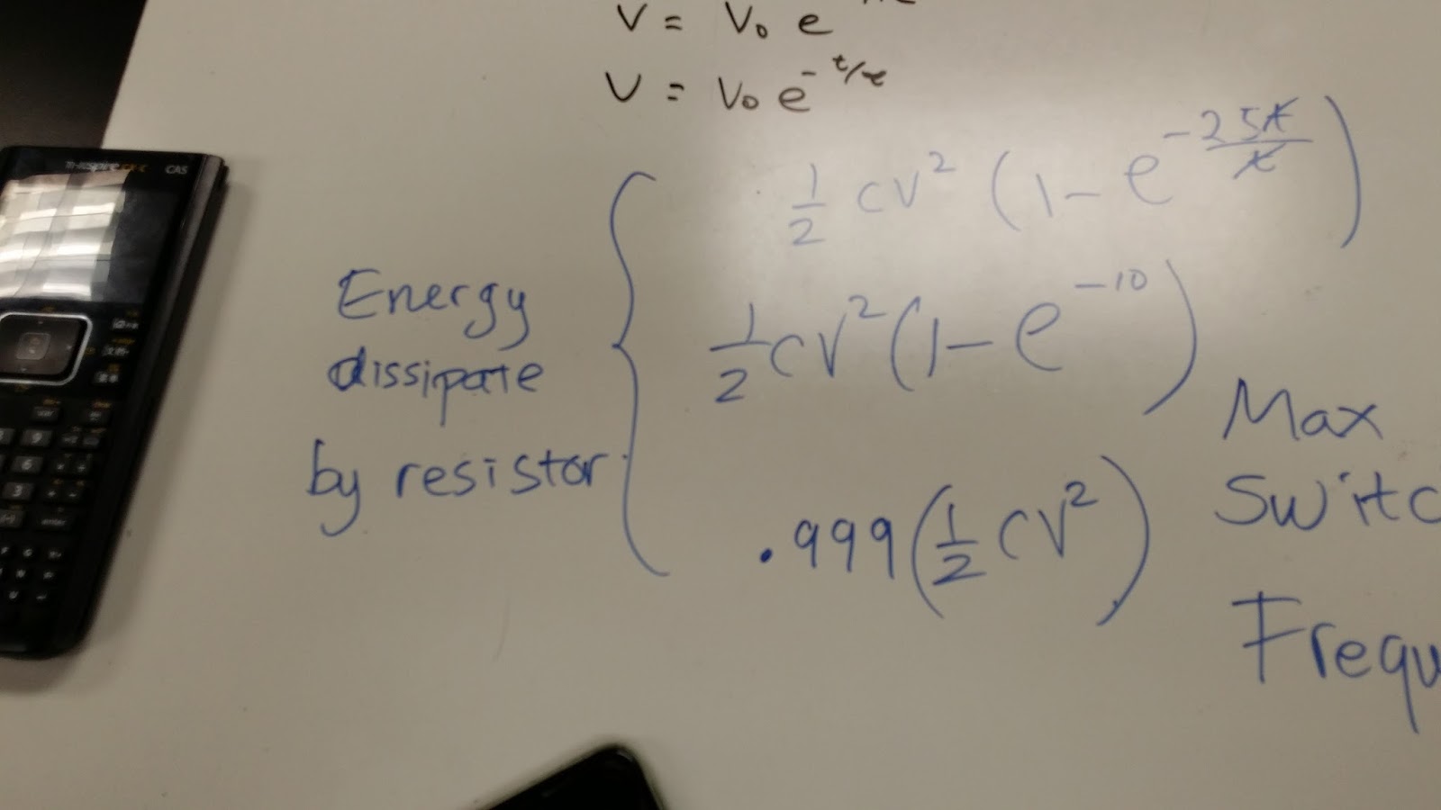
Calculating the Energy dissipated by the resistor in a source free RC circuit after time of 5 time constants ( Which is where engineers say is the time needed to completely discharge a capacitor):
Calculating the maximum switch frequency of a capacitor:
Another problem calculating voltage as a function of time in the case of discharging capacitor in a free source RC circuit:
Calculating the current of a discharging inductor in a source free RL circuit:
"Passive RC Circuit Natural Response":
Pre-lab:
Calculating the theoretical time to charge and discharge the capacitor in the designated circuit and a diagram of the circuit:
Value of the first resistor (theoretical 2k ohms):
Value of the second resistor (theoretical 1k ohm):
Oscilloscope on the charging capacitor:
Oscilloscope on the discharging capacitor:
Oscilloscope on the square wave:
a gif of the square wave:
The values:
maximum potential difference in the capacitor when it is fully charged:
"Passive RL Circuit Natural Response"
Prelab:
Oscilloscope for the square wave:
(In the wavegen square wave frequency is set to 1.8khz):
Summary:
- 5 time constant is a good estimation both theoretically and experimentally for time to completely discharge a capacitor
- Trigger switch is a good tool to utilize in waveform if we want to record something that happens once in a short period of time, such as charging or discharging a capacitor.
- We could calculate inductance from the time for the inductor to discharge and the thevenin resistance of the circuit (L~R*t_discharge/5)
Class Activities:
Calculating the equivalent inductance of multiple inductors:
Calculating the Energy dissipated by the resistor in a source free RC circuit after time of 5 time constants ( Which is where engineers say is the time needed to completely discharge a capacitor):
Calculating the maximum switch frequency of a capacitor:
Another problem calculating voltage as a function of time in the case of discharging capacitor in a free source RC circuit:
Calculating the current of a discharging inductor in a source free RL circuit:
"Passive RC Circuit Natural Response":
Pre-lab:
Calculating the theoretical time to charge and discharge the capacitor in the designated circuit and a diagram of the circuit:
Value of the first resistor (theoretical 2k ohms):
Oscilloscope on the charging capacitor:
Oscilloscope on the discharging capacitor:
Oscilloscope on the square wave:
a gif of the square wave:
The values:
maximum potential difference in the capacitor when it is fully charged:
values:
"Passive RL Circuit Natural Response"
Prelab:
Oscilloscope for the square wave:
Summary:
- 5 time constant is a good estimation both theoretically and experimentally for time to completely discharge a capacitor
- Trigger switch is a good tool to utilize in waveform if we want to record something that happens once in a short period of time, such as charging or discharging a capacitor.
- We could calculate inductance from the time for the inductor to discharge and the thevenin resistance of the circuit (L~R*t_discharge/5)
Subscribe to:
Posts (Atom)